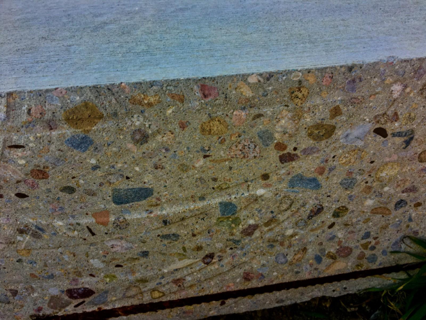
The hydrated cement matrix surrounds a wide variety of colorful aggregates.
The hydration of cement in concrete
Concrete has been considered a multi-scale material dating back to its first use and documentation in the catalogs of Egyptian and Roman histories. The strength and durability of concrete is reliant not only on the heterogeneous nature of the macro-composite, but more importantly, on micro-composite gels and (recently discovered) nanostructures. The interest in the latter grew within the last two decades, due to advances in manufacturing reactive nano particles, specifically nano silica.
The larger concrete composite, a heterogeneous material, can be considered a four-component material, both in a fluid (plastic) and hardened (cured) states. The plastic state consists of 1) rock and sand, which make up the granular skeleton; 2) cement powder; 3) H2O and admixtures; and finally 4) the entrapped and entrained air. As the concrete cures from plastic to hardened states, the cement paste (components 2 to 4) morphs from the fluid-like state to a rock-like state. In the hardened state, concrete is a composite material made up of stiff aggregate (rock and sand) embedded in a softer matrix (hydrated cement paste).
Cement strength is based on reactions between H2O and the several successive cementitious phases that occur during hydration. To understand the importance of these reactions, it is first important to identify the stages at which these reactions take place in the cement hydration process. The time to reach those stages and the length of time in those stages of cement hydration varies between cement compositions. The development of the crystal structures and gels correlates closely with the changes in temperature that occur over time during the cement hydration process, so temperature is a useful tool in tracking the process. The temperature of cement hydration process is illustrated in Figure 1 [4].
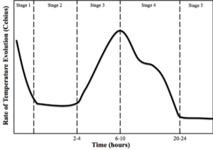
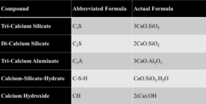
Figure 1 — The five stages of the cement hydration process: Stage 1, Mixing; Stage 2, Dormancy; Stage 3, Acceleration; Stage 4, Deceleration; Stage 5, Densification [4] The abbreviated compounds commonly found in hydrated cement are defined in Table 1. The main chemical components from Portland cement that are of concern for cement hydration are the tri-calcium silicates (C3S) and di-calcium silicates (C2S). The concentration of the C3S exceeds that of C2S, making up approximately 50–70% and 15–30%, respectively, of total Portland cement chemical composition [4, 5]. In conjunction with a smaller amount distribution, the C2S can be found in the form of nests or clusters included in the C3S. The greater availability of C3S over C2S ensures an earlier reaction time for the C3S in the presence of H2O. Finally, due to its hexagonal-like geometry, the C3S will have more surfaces to facilitate initial reaction with H2O when compared to the rounded structure of the C2S [5]. When H2O is mixed with cement there is an initial production of ettringite and precipitation of CH. These two crystalline compounds, in combination, form (over time) a surface layer covering the cement particles, which acts as a diffusion barrier to H2O [5]. The initial release of energy from these reactions causes a spike in the temperature of the mix during Stage 1 shown in Figure 1. The formation of these early products contributes little to concrete early or later strength development, or durability against ASR. In Stage 1, tri-calcium aluminate (C3A) reacts with H2O to form calcium aluminate hydrate (ettringite) in the cubic (C3AH6) or the hexagonal (C4AH12) crystalline structures shown in Figure 2 and described by

Equation 1
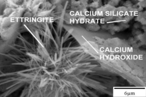
Figure 2 — Hydrated cement composite under scanning electron microscopy [6]
Table 1 — Abbreviated cementitious compounds [4]
In Stage 2, the surface layer described in Stage 1 germinates and begins to coat the cement particles. As the surface layer grows in thickness, it slows the access of H2O into the inner layers
of the anhydrous cement particle, thereby decelerating the hydration reactions. Within the surface layer, the reaction rate is maintained until the free H2O approaches exhaustion. Gradually, the coating over the cement particle becomes thicker, and the rate of reaction decreases to a point where the cement hydration approaches a period of dormancy. Preservation of the dormancy stage is a necessity for the commercial concrete industry, as this is the stage during which the contractor places the fluid concrete into forms. As the dormancy stages continues, residual water within the surface layer increases the amount of hydrated product but the surface layer contains the anhydrous product, keeping the concrete in a fluid state. As the cement hydration process continues, more H2O reacts with more of the cementitious components, the C3S and C2S, to form calcium hydroxide (CH) and calcium-silicate-hydrates (C-S-Hs). The calcium silicates do not hydrate in the solid state, but the anhydrous silicates probably first release a CH solution and then react to form less soluble hydrated silicates, which separate out of the supersaturated solution [5]. Richardson supported this, showing that the C-S-H forms from solution after the CH separates out [7]. The chemical reaction below shows the principal reaction of H2O and C3S in Stage 2 in Equation 2:

Equation 2
Within the hydrated and cured cement matrix, CH has a greater potential for solubility and growth as compared to the other hydration products in the presence of H2O, [5]. The CH crystal can form into a myriad of shapes that include plate-like, hooded, and fractured. An example of a plate-like CH crystal is shown in Figure 2. During Stage 2, CH and C-S-Hs grow within the initial hardened surface layer to the point where they break through the germinated surface layer over the anhydrous cement. Once the surface layer is broken, H2O can react with the remaining anhydrous cement and more crystals develop. The reaction products in Equation 2 release heat to the surroundings to increase the temperature, and initiate transition from Stage 2 (Dormancy) to Stage 3 (Hardening/Acceleration).
During Stage 3, CH grows within the cement paste, giving the cement paste its initial, strength. After the CH precipitates, the remaining solution is supersaturated with calcium oxide, CaO (Ca) and silica, SiO2 (Si). As the Ca/Si ratio climbs between 0.7 and 3.0, the H2O in this supersaturated solution is consumed, see Appendix B for more detail [8]. C-S-Hs polymerize and harden into globular masses with successive layers developing into the backbone of concrete strength and durability.
The C-S-H gel has two distinct forms that are categorized by development either early (outer- product, OP) or late (inner-product, IP) [7]. The early C-S-Hs are the impure form of the gel with a high density of pores [8]. The residual H2O bound in these pores accounts for a large portion of concrete later strength reduction and chemical degradation. The proportion of this bulk (liquid) H2O is decreased if it is incorporated into the reaction of excess cementitious and pozzolanic reactions.
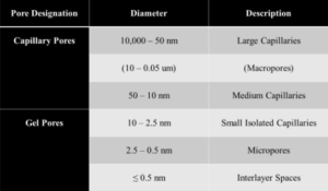
The successive layers of the C-S-H are saturated with H2O at early stages of hydration as shown in Figure 3. Once the surface area of OP C-S-H starts increasing, free H2O not bonded to the cement particle migrates through the porous HCM to the residual anhydrous cement. While the anhydrous cement absorbs H2O, the OP C-S-H gel cures and hardens and the C-S-H arranges itself into clay-like sheets. Figure 3 illustrates the calcium oxide (CaO) layer enclosed by pairing silicon tetrahedra. Each of these C-S-H sheets is connected over inter-layer space by bridging silicon tetrahedra, which establishes the framework for the C-S-H gelled network. The orientation of the C-S-H structure (interlayer space and pore structure) determines the structural integrity of the HCM and the final concrete [8, 7]. Throughout the OP C-S-H structural web, there are a myriad of pore types and sizes. A listing of pore types and sizes is shown in Table 2. These pores, if filled with nano silica particles (unreacted) or with the reaction products of nano silica treatment, could offer more resistance to the strength and durability of concrete.
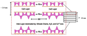
Figure 3 — Schematic of the C-S-H layers
Table 2 — Classification of pore size in hydrated cement composite [4]
The other type of C-S-H formed is the late product or IP C-S-H. This product will be a more pure and denser version of the previous OP C-S-H [7]. The density, and therefore the eventual ability
of the cured concrete to resist compressive loads, increases as the hydration products increase for IP C-S-H. In Stage 3, the majority of the OP C-S-H is formed from the C3S, while only a small
trace of C2S reacts [5]. In other words, Stage 3 will primarily have early OP C-S-H and trace amount of late IP C-S-H.
When the C3S reacts with H2O and starts to produce the C-S-H structures, the C-S-H lamellae and microstructure grow out into the space between adjacent particles, as well as into the cement
particle. During the fourth stage of cement hydration, reaction of C3S slows the reaction of C2S increases.
The reaction of the C2S develops slowly due to lower abundance, lower surface area, and the fact that it is often embedded in the C3S. By way of its slower reaction, due to a lower percent composition in cement and a lower surface area than the C3S, the C2S releases less heat to the surroundings, compared to the C3S [5]. As previously mentioned, C2S yields growth of late IP C-S-H. Therefore, as the propensity for C2S to react increases, so does the concentration of late IP C-S-H. For this reason, heat from C2S formation is difficult to measure, as the heat balance of the whole process is dominated by the reaction of C3S.
The heat exchange for both C3S and C2S are listed in Table 3; a lower heat of hydration is shown for the C2S when compared to C3S [4]. Even though the reaction of the C2S is slower and releases less energy, the reaction yields less CH and a denser C-S-H denser meaning that there is less CH and fewer/smaller pores intermingled in the C-S-H. This denser C-S-H crystal can resist more compressive loads than the CH [9, 10, 11]. The reaction for the C2S and H2O in Equation 3 is:

Equation 3
Table 3 — Isothermal heat of hydration of common cementitious reactions [4]
In Stage 4, there is a significant reduction in heat due to the reduction of the primary cementitious (C3S) reactions. There is a transition period from Stage 3 where the majority of the dissolving components were C3S to Stage 4 where the majority is C2S. The second layer (diffusion layer) that has developed at the outer surface of the hydrating cement particles decreases the amount of H2O that can migrate to the inner anhydrous cement. The residual water within the hydrating cement matrix reacts with residual C3S, but at a certain time the majority of the constituents left to react comes from the C2S.
In Stage 5, Densification, there is a greater decrease in the C3S reactions and therefore, a measurable decrease (based on the equipment used in this PhD dissertation) in temperature that leads to a temperature plateau. The heat of hydration curve, shown in Figure 1, illustrates this heat plateau. Stage 5 of the cement hydration process continues as long as H2O and sufficient reacting compounds are present. Therefore, the longer a sample is allowed to cure with silica and H2O present, the higher the concentration and density of C-S-H. This same phenomenon is found in commercial concrete applications where the original concrete design strength at 28 days is far exceeded by the strengths measured years after the structure has cured under favorable conditions.
In addition to the cementitious reactions in Equation 2 and Equation 3, a pozzolanic reaction occurs with the addition of silica into the pore solution. A pozzolanic material, Class F fly ash, served as a basis of comparison for laboratory and field trials during the research for this PhD dissertation. The Silica Fume Association stipulates that a pozzolanic material will not gain strength when mixed with H2O, while a cementitious material will hydrate and gain strength [11]. The pozzolanic material assists in the development of C-S-H through a pozzolanic reaction with the CH, such that:

Equation 4
While commonly used and current pozzolanic materials have a tendency to increase later strengths in concrete, they have also been shown to significantly reduce early strengths. In performance-based concretes (with secondary cementitious and pozzolanic materials) this reduction in early strength can be attributed to a dilution effect where the Class F fly ash has replaced a portion (by mass) of the OPC in performance-based concrete, thus decreasing the cementitious reactions, heat and early strength.
Bentz found that the significant benefits gained by using micrometer-sized pozzolanic materials were from the densification of the C-S-H gel and the HCM of concrete [9, 10]. Bentz showed that, in addition to densifying the body of concrete within the HCM, silica in the interfacial transition zone (ITZ) packs more efficiently than cement particles. The ITZ is the region where the aggregate surface meets the cement matrix. Normally, the amount of cement paste at the ITZ is less than that in the body of the specimen. This is known as the wall effect, a thinning of the cement paste at this ITZ (that is, on the surface of the aggregate) due to the higher surface area of the aggregate. Because of this limited availability of paste, it is desirable to ensure that the paste that is available contains a more homogenous mixture of silica and calcium, which will increase the strength of the cured cement matrix [12]. This homogeneity contributes to a tougher and more durable C-S-H gel. Silica-enriched cement at the ITZ region is denser then the cement paste without the addition of silica. Hydration of the densified paste at the ITZ improves the bonding of the aggregate into the HCM. Furthermore, as with the ITZ, within the body of the HCM and concrete composite, excess free silica contributes to the increased density through pore packing. All of these phenomena combined lead to a concrete composite that is stronger and more durable. Ultimately this PhD research was to study the impact of a newer pozzolanic material, nano silica, which may offer better performance and/or enhance the performance of industry standard pozzolanic materials.
References
1. US-DOI. Materials in Use in the U.S. Interstate Highways. USGS Department of the Interior, 2006.
2. Thomas, M., B. Fournier, and K. Folliard. Report on Determining Reactivity of Concrete Aggregates and Selecting Appropriate Measures for Preventing Deleterious Expansion in Concrete Construction. Departmant of Transportation – FHWA, 2009. p. 1–22.
3. Kuennen, T. FHWA Research Zeroes in on Concrete Nanotechnology. Concrete Products, 2010. www.concreteproducts.com/mag/concrete_fhwa_research_zero.
4. Mindess, S., J. Young, and D. Darwin. Concrete. Prentice Hall, 2003. 2: p. 57–120.
5. Taylor, H.F.W. Cement Chemistry. Thomas Telford Books, 1997. 2: p. 89–226.
6. Belkowitz, J., and D. Armentrout. An Analysis on Nano Silica in Cement Hydration. National Ready-Mixed Concrete Association Conference Proceedings on Concrete Sustainability, 2010: p.1–15.
7. Richardson, I. The Calcium Silicate Hydrates. Cement and Concrete Research, 2007. 38: p.137–158.
8. Allen, A., J. Thomas, and H. Hennings. Composition and Density of Nanoscale Calcium-Silicate-Hydrate in Cement.Nature Materials, 2007. 6: p. 311–316.
9. Bentz, D. and Garboczi, E. Simulation Studies of the Effects of Mineral Admixtures on the Cement Paste-Aggregate Interfacial Zone. ACI Materials Journal, 1991: p. 518–529.
10. Bentz, D. and Stutzman, P. Evolution of Porosity and Caclium Hydroxide in Laboratory Concretes Containing Silica Fume. Cement and Concrete Research, 1994. 24: p. 1044–1050.
11. Holland, T. Silica Fume User’s Manual. Department of Transpotation — FHWA, 2005: p.8–13.
12. Manzano, H., J. Dolado, A. Guerrero, and A. Ayuela. Mechanical Properties of Crystalline Calcium-Silicate-Hydrates: Comparison with Cementitious C-S-H Gels. Physical State Solutions, 2007. 204: p. 1775–1780.
Copyright Intelligent Concrete, LLC 2017.
